Genapp -- Data-model based generator of an application prototype
Introduction
This documentation has been created to document and provide a solution overview of the Genapp tool – data-model based application prototype generator, which has been developed as a Research Project at Faculty of Mathematics and Physics, Charles University in Prague.
Motivation
In modern software systems, managing and sharing data across different technologies and platforms can be challenging. These difficulties often come from the variety of ways data structures are designed, differences in how details are represented, and issues with compatibility. To address these challenges, Dataspecer tool has been developed at the Faculty of Mathematics and Physics. Its primary goal is to standardize and streamline the process of creation, modeling and management of data specifications. By having standardized and easily created data specifications, it becomes much easier to ensure that the data we work are interoperable.
With ongoing development and new features, Dataspecer tool’s functionality is now not limited to the creation and management of data specifications. Dataspecer can also generate various artifacts for data structure models defined within a data specification, all that while maintaining semantic relationships. The data-driven approach, along with the tool’s current features, not only helps with designing and managing data specifications, but also makes it possible to use the generated artifacts for other purposes or serve as an example for entirely new generated artifacts.
The main goal of this project is to design and implement a tool that can automatically generate one such new artifact – an entire application prototype based on a data specification from Dataspecer. This prototype will help verify whether the data model meets business requirements and can serve as a foundation for further system development.
Key Concepts and Decisions
As stated in the previous section, the aim of this project is to design and implement a tool that can allow a user to automatically generate an application prototype based on a data specification created in Dataspecer. Before generating the actual application prototype code, Dataspecer data specifications were analyzed to determine the scope and range of operations to be generated.
CRUD Operations
The first key concept for the prototype generator is the decision to focus solely on generating CRUD operations – Create, Read, Update, Delete.
CRUD operations are essential building blocks of the majority of information systems. They represent the basic way, in which data can be created, manipulated and managed within a system. Given that most systems require a certain level of consistent data handling, the generation of CRUD operations ensures that the generated application prototype will provide a support for most used and common data interactions.
Additionally, CRUD operations are tightly tied to a data structure that they are performed on, i.e. the static declaration of a data structure. These operations are relatively straightforward with well defined semantic meaning and may be generally applied on most data structures. In order to generate these operations, the generator only needs to consider the static description and is not required to capture any dynamic, context-specific business processes or highly specific data interactions. While infering and generating context-specific operations would make the generated prototype more customized, it might also lead to incorrectly inferred context-specific operations. For this reason, a decision has been made to only support the generation of CRUD operations, which can, however, be applied in broader contexts.
Therefore, CRUD operations are ideal candidates for operations to be generated within automatic application prototype generator, regardless of the specific data specification context or its domain.
Capability and Aggregate Concepts
In the previous section, we stated the reason why the operations supported by application prototype generator are limited to the CRUD operations. However, from the perspective of the user of the generated application prototype, it is usually not necessary to generate all CRUD operations for all data structures defined in a data specification. The necessity of performing an operation depends on the specific use case and role of the data structure. While some data structures serve mainly for the purpose of data creation and modification, others may be used only as various ways to display processed data.
The need for flexible operation selection has been reflected in the design of the prototype generator, which allows the generator’s user to configure the subset of operations to be generated for each data structure. While the specific process will be presented later in this document, we now define two key concepts needed in order to be able to use Genapp tool.
Capability: A capability is a type of CRUD operation, which is relevant within the context of the generated application prototype.
Simply put, each capability represents an operation performed on a data structure, which is meaningful for the user of the generated prototype and for which it makes sense to be generated.
Aggregate: An aggregate refers to a data structure defined in a data specification, which is the subject of a specific capability, i.e. the data structure on which the specific operation is performed and for which it makes sense to be included in a generated application prototype.
Application Graph
By association of capabilities with aggregates, the prototype generator user is given a key tool to specify the model of the application that should be generated by the generator.
The set of (capability, aggregate) tuples defines essential functional units of the generated application prototype. Each such pair results in an generated capability specific for the aggregate. Although the generator could already generate a prototype, the generated functional units would be isolated from each other. Therefore, this concept needs to be extended to provide a way to interconnect different functional units. This extension leads to the definition of application graph:
Application Graph: An application graph is a directed graph, which represents a model of the application prototype to be generated.
Per the definition, an application graph contains nodes and edges, where:
- nodes – set of (capability, aggregate) tuples,
- edges – set of directed transitions between nodes.
Each node represented in the application graph corresponds to a separate and isolated functional unit to be generated. The capability of a node indicates the operation to be generated and aggregate corresponds to a data structure on which the capability should be performed on.
Each edge tells the generator that the generator user wants to be able to transfer between nodes and thus create an interaction within the generated prototype.
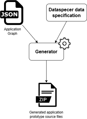
Since the Application Graph is one of the two inputs of the application prototype generator, it is the fundamental concept needed to be able to work with Genapp application prototype generator tool.
Application Graph Specification
The Application Graph can be defined as a document in JSON format with the structure specified by the JSON schema or available within Dataspecer – Application Graph specification. The Application Graph interface is translated to the following set of Typescript types:
interface ApplicationGraphType {
    label: string;
    dataSpecification: string;
    datasources: Datasource[];
    nodes: ApplicationGraphNodeType[];
    edges: ApplicationGraphEdge[];
}

type ApplicationGraphNodeType = {
    iri: string;
    label: LanguageString; // mapping { [ language: string ]: string }
    structure: string;
    capability: string;
    config: NodeConfiguration;
}

type ApplicationGraphEdge = {
    iri: string;
    source: string;
    target: string;
    type: ApplicationGraphEdgeType; // enumeration with values "aggregation", "redirect", "transition"
}

type NodeConfiguration = {
    starting?: boolean,
    pageTitle?: LanguageString,
} & Record<string, any>;

type Datasource = {
    label: string;
} & {
    format: "json" | "rdf" | "csv" | "xml" | "local";
    endpoint: string | {
        read: string;
        write: string;
    }
};
Each Application Graph contains the following properties:
labelrepresents a graph name or human-readable graph reference,dataSpecificationstring has to contain the IRI of the Dataspecer data specification, for which the application will be generated. Data specification IRI can be retrieved from data specification detail found in Dataspecer specification manager.datasourcesrepresents a collection of objects, where each object describes, where the actual data for the application should be retrieved from / written to. Additionally, it also defines the format of data, and thus specifies the type of the data layer to be generated. NOTE: Currently, only first datasource in this collection is considered. Additionally, only"rdf"format endpoints are supported despite the possible definition of different formats.nodesis a collection of application graph nodes. The more detailed description follows below.edgesis a collection of application graph edges. The more detailed description follows below.
Each Application Graph Node is specified as follows:
iriis a graph node identifier, which has to be unique within a graph. The supported pattern for node IRI is"https://example.org/application_graph/nodes/<decimal identifier>". A graph with duplicate node IRI identifiers will be considered invalid and will not generate any application prototype.labelis a user-defined language-mapped label for given node. It serves for human-readable node identification.configrepresents an object for custom node configuration. Currently, using the config, the user can set a custom, lanugage-mapped node title, which will be used by the generator to customize the generated UI of the given node.structurerefers to an aggregate IRI, which comes from Dataspecer data specification and which is subject to the capability of this node. Structure IRI has to match pattern"https://ofn.gov.cz/schema/<ID of the structure model from Dataspecer>".- NOTE: Genapp tool uses aggregate metadata (such as name of the aggregate) to generate human readable labels. Although Genapp tool is able to distinguish different aggregates with the same name (i.e. two aggregates with different IRI identifiers, but with same name), it is recommended to use unique aggregate names.
capabilityrefers to the capability to be performed on the aggregate of this node. Capability IRI has to match one of the following values:"https://dataspecer.com/application_graph/capability/list","https://dataspecer.com/application_graph/capability/detail","https://dataspecer.com/application_graph/capability/create-instance","https://dataspecer.com/application_graph/capability/edit-instance","https://dataspecer.com/application_graph/capability/delete-instance".
Each Application Graph Edge is specified as follows:
iriis a graph edge identifier, which has to be unique within a graph. The supported pattern for edge IRI is"https://example.org/application_graph/edges/<decimal identifier>". A graph with duplicate edge IRI identifiers will be considered invalid and will not generate any application prototype.sourcerefers to the graph node IRI where the transition will begin. Has to match one of the nodes of the graph.targetrefers to the graph node IRI where the transition will end. Has to match one of the nodes of the graph.typerepresents the type of the generated transition edge. Supported values are:"transition"– generates a UI element in the generated prototype, which the user has to interact with in order to trigger the transition from one node to another (usually a button)."redirect"– generates a transition, which is triggered automatically after a condition is met (e.g. when create capability finishes successfully, a redirect to list capability is triggered)."aggregation"– NOTE: This type of edge transition is not supported in the current version of Genapp tool.
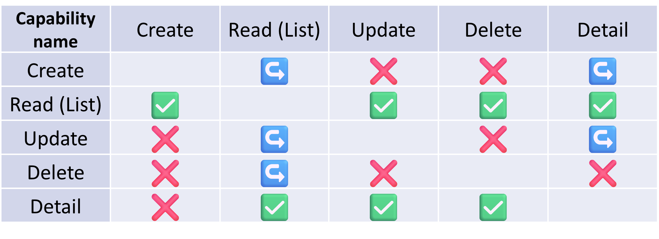
The specification of application graph edges is further refined by the meaning / usefulness of a transition in the generated prototype. For example, a transition from an aggregate creation node to the same aggregate edit node is not really meaningful as the instance has not even been created yet. For an aggregate, we therefore define the set of supported edges, which are meaningful for the end user. Only these edges are allowed to be generated. Please refer to the table below to find out the allowed transitions between different nodes. Rows should be interpreted as source nodes, whereas columns as target nodes. In this table:
the ✅ symbol indicates a “transition” edge type is allowed between the nodes with given capabilities,
the ↪️ symbol indicates a “redirect” edge type is allowed between the nodes with given capabilities,
the ❌ symbol indicates that the transition is typically not meaningful for the end user, and is not allowed
Below are the examples of an application graph node, an edge and a datasource (in respective order):
{
    "label": {
      "en": "Node label",
    },
    "iri": "https://example.org/application_graph/nodes/1",
    "structure": "https://ofn.gov.cz/schema/<ID of the structure model from Dataspecer>",
    "capability": "https://dataspecer.com/application_graph/capability/<capability identifier>",
    "config": {
      "pageTitle": {
        "en": "A node title to be shown"
      }
    }
}
{
    "iri": "https://example.org/application_graph/edges/1",
    "source": "https://example.org/application_graph/nodes/1",
    "target": "https://example.org/application_graph/nodes/2",
    "type": "transition"
}
{
    "label": "<datasource label>",
    "endpoint": "<endpoint url of the datasource>",
    "format": "rdf"
}

OR

{
    "label": "<datasource label>",
    "endpoint": {
        "read": "<endpoint url of the datasource for read operations>",
        "write": "<endpoint url of the datasource for write operations>"
    },
    "format": "rdf"
}
User manual – How to generate an application prototype?
The main goal for a user of the Genapp tool is to generate an application prototype. In order to achieve this goal, the user has to perform a set of the following steps:
Data specification and data structure models creation
First, the user needs to get a data specification to work with. Using the Dataspecer tool, it is possible to either choose one of the existing specifications from the list or create a specification. Should the user decide to choose one of the existing specifications, then the following steps in this section may be skipped. To create a specfication, the user can click the
Create specificationbutton, which will lead to the creation of a new, empty, custom-named data specification.To create a custom specification, which will be later used for application prototype generator, you can follow this tutorial despite slight changes in Dataspecer tool UI.
Note / Tip: For easier and faster navigation in the following step, it is recommended to add a tag to a data specification, or copy the data specification IRI (this option is available on data specfication detail screen).
Using Dataspecer manager to launch generator
Once the user has created or chosen a data specification to work with, the next step is to navigate to Dataspecer manager tool.
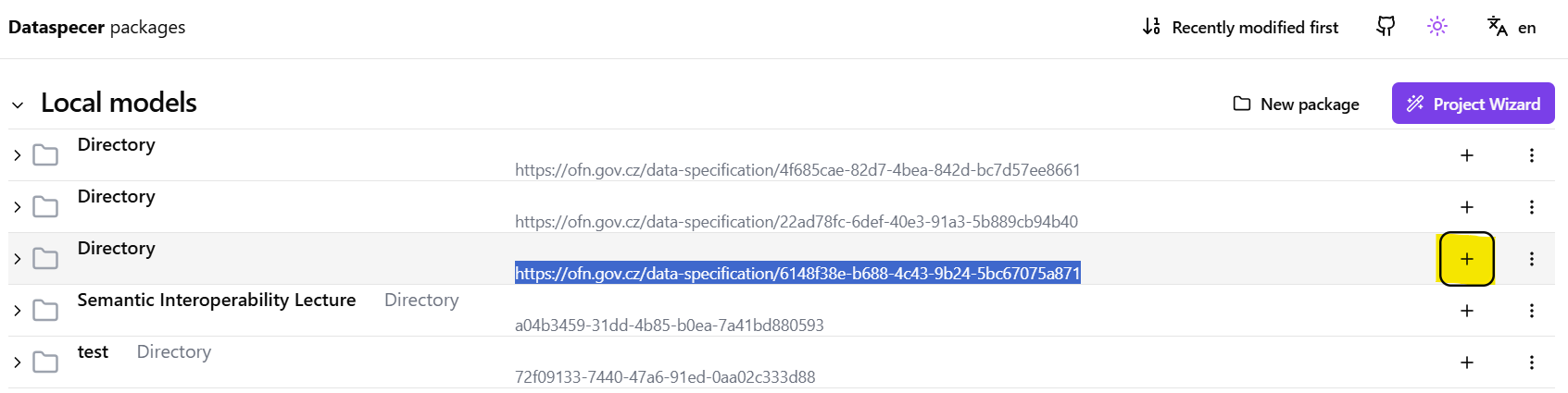
Within the Dataspecer manager, the user needs to find and access the data specfication created / chosen in the previous step. To find the data specification in the list of all available specifications, use the tag or the data specification IRI saved in the previous step. Once the data specification is found, click the “+” button on the right side and choose “Application graph” option from the proposed options list. Please refer to the screenshots below for an illustration.
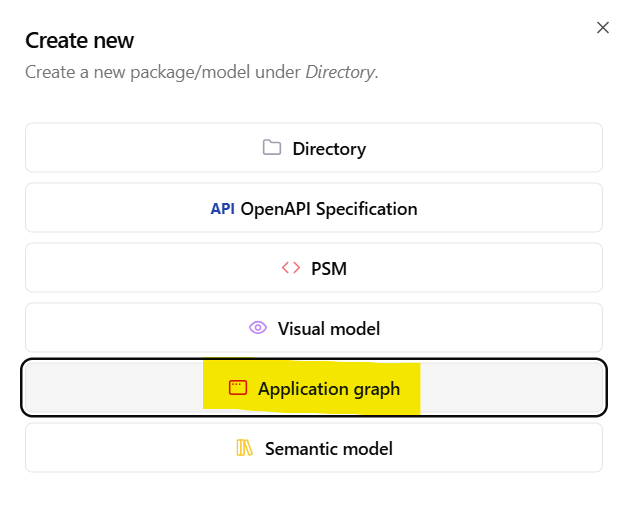
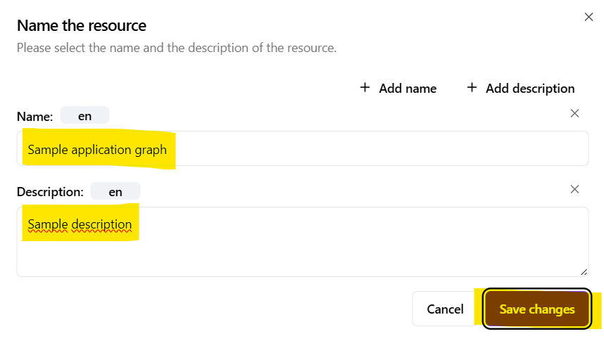
- After clicking the
Application graphbutton, the user is asked to provide a language-tagged graph name and description. These serve only for easier graph identification within the data specification artifacts list. Click on theSave changesbutton once application graph name is provided. This will lead to a creation of an empty application graph which needs to be edited in order to generate a useful application prototype.
Create an Application Graph
As mentioned in the previous step, the created application graph is empty and does not contain any nodes / edges to be generated. Therefore, the user is required to complete the application graph which complies with the specified application graph schema. By modifying the empty application graph, the user is able to capture and express the requirements on the generated application prototype.
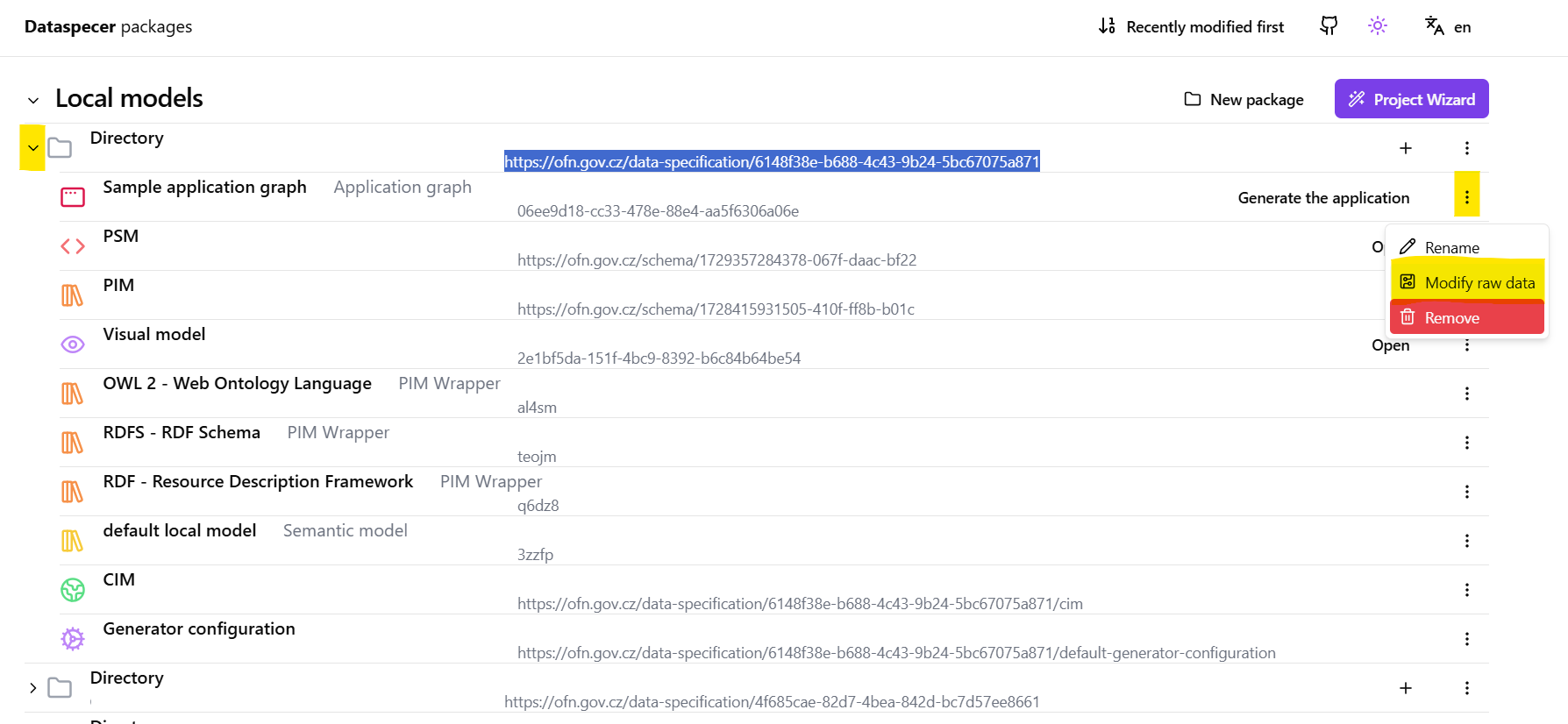
Once the previous step is completed and an empty application graph created, find again the data specification in the Dataspecer manager tool and click on the “>” symbol on the left side of the screen. (Tip: Select “Recently modified first” option on the top of the manager window to be able to quickly find the data specification).
The list of available artifacts for the data specification now contains the empty application graph artifact with the name defined in previous steps. To modify application graph content, click on the “three dots” icon next to the
Generate the applicationbutton on the right side of the screen. Then, click theModify raw databutton as shown in the screenshot below.
- An application graph editor will open. The user is now able to edit the JSON format definition of the application graph according to the application graph schema. To facilitate the definition of the application graph, it is highly advised to use its JSON schema – application graph specification. The user can import the schema to the editor by pasting the following line into the graph editor.
"$schema": "https://schemas.dataspecer.com/adapters/application-graph-model.v1.0.schema.json"
Using the JSON schema of the application graph, the editor will be able to better suggest missing properties and will provide examples of expected values.
Within the editor, complete the application graph definition by adding all desired application nodes (i.e. functional application units), application edges (i.e. transitions between different nodes) as well as the remaining application graph properties. For more detailed graph description, interface and expected values, please refer back to Application Graph Specification.
After all application graph modifications are finished, click on
Savebutton and exit the graph editor.Click the
Generate the applicationbutton on the right side of the page for the corresponding application graph to start application prototype generation. The application prototype generator has now started generating the application prototype based on the provided data specification and the provided application graph.Wait for the application generator to finish the process of prototype generation. Please refer to the next section to learn how to run the generated application prototype.
Running the generated application prototype
The application prototype generated based on the data specification and the user’s definition of an application graph is available as a ZIP archive of generated source files. Therefore, it is important to note that the application is not deployed or executed immediately after having been generated and must be built and ran on the user’s local machine.
Therefore, this section provides a brief manual on how to run the generated application on a local machine. The user is advised to use a terminal to install and run the application prototype.
Once the generation has completed, the generated application source files will be provided to the user as a ZIP archive available for download. Download the ZIP archive and navigate to the location, where the ZIP has been saved.
Extract all files from the ZIP archive.
Navigate to
generatedAppsubdirectory, which represents the root directory of the generated application.If not done so, open the terminal in the
generatedAppdirectory.Run
npm installcommand to install application dependencies and wait for the installation to complete.Run
npm run startcommand to start the application prototype.
The generated application prototype is currently generated as a Create React App project. npm run start command internally starts a local React development server, which is responsible for serving the application locally. Usually, http://localhost:3000 will be used by the server to serve the application.
Solution overview
In the previous sections, the key concepts were introduced and explained, and a user manual which outlines the expected usage was presented. What now follows is an overview of the architecture of the generated application prototype as well as the architecture of the generator itself.
Generated Application Architecture
The generated application prototype follows a Three-Tier architecture. The generated code is therefore organized into three separate tiers / layers, each with a separate responsibility:
- Data Access Layer,
- Application Layer,
- Presentation Layer.
Folder Structure
The folder structure of the generated application prototype also follows this separation, where each of the layers is stored in the corresponding src subdirectory:
data-layer,application-layer,presentation-layer.
Data Access Layer
Data Access Layer is the layer which is responsible for the actual execution of data operations and communication with the specified datasource. The generated data access layer contains readers / writers for the nodes specified in the application graph. Moreover, the specific data access implementation corresponds to the format of data specified within application graph datasource.
NOTE: Please note, that only "rdf" format data sources are supported despite the possible definition of different formats.
Application Layer
Application layer is responsible for the execution logic of corresponding capabilities performed on aggregates. Within the generated application prototype context, the responsibility of the generated application layer is to
Presentation Layer
The presentation layer is responsible for visual interaction with a user of the generated prototype. Based on the specific capability, the presentation layer is responsible for displaying data returned from the datasource, or for accepting and processing the input from the user.
Within this project, the generated presentation layer components correspond to the React components.
Prototype Generator Architecture
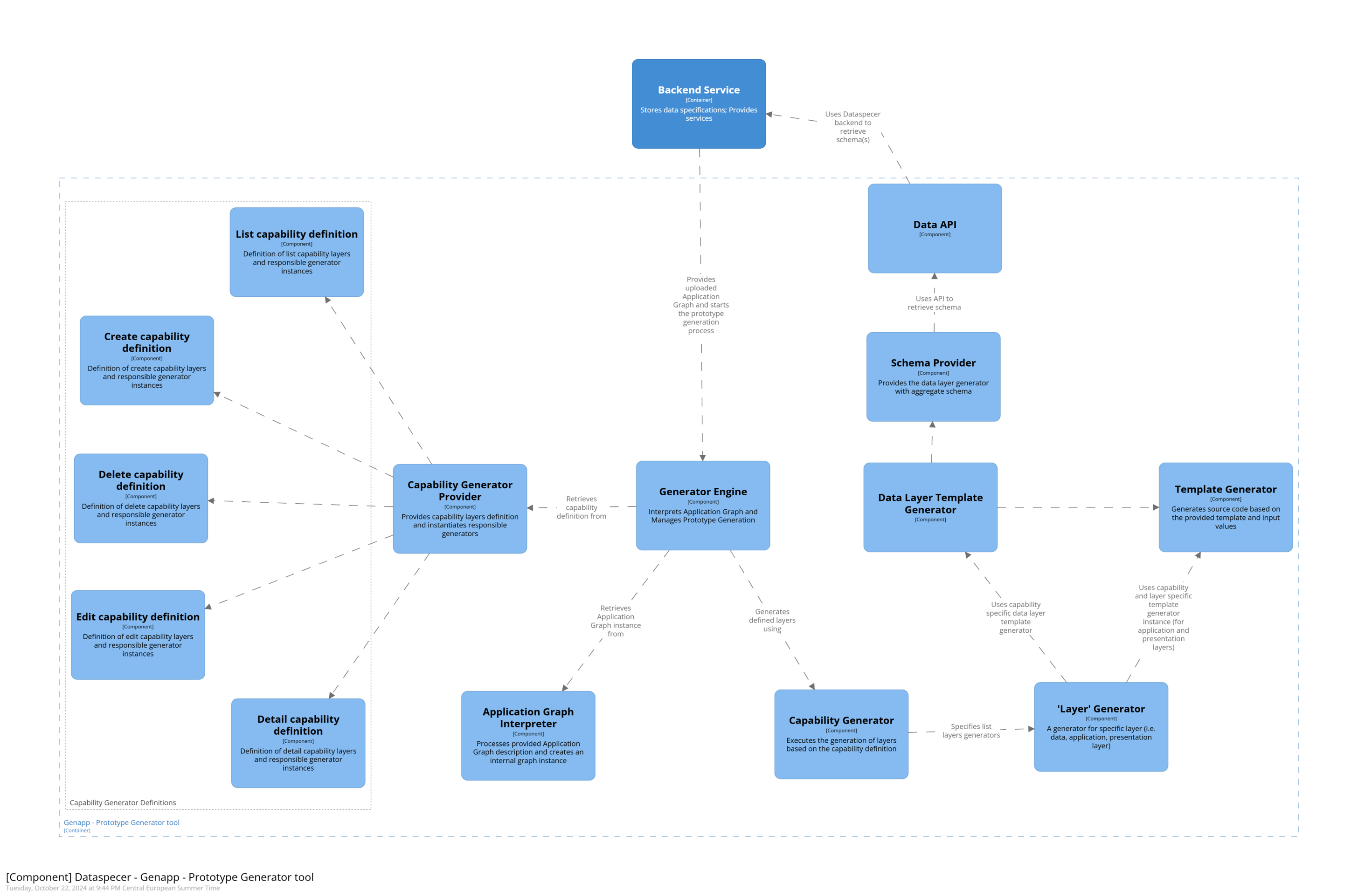
The architecture of the generator is structured into multiple logical components, which partially correspond to the individual steps required for prototype generation. One of the main goals of this logical separation of the generator’s code structure was to ensure an easy extensibility for new types of supported operations (i.e., the ability to add new capabilities), including the ability to define their internal structure and layers independently of remaining capabilities. Current architecture of the generator enables this by allowing for separate definitions of operations, within which it is possible to specify the layers to be generated as well as the instances of generators responsible for the actual generation process.
For a more detailed overview of the code structure and the logical separation of different components, along with a comprehensive description of the classes and methods, please visit the technical documentation page.
Generator Engine Component
ApplicationGenerator
The Genapp tool architecture is centered around the ApplicationGenerator class located in src/engine/app-generator.ts source file. generate() method of this class represents the entrypoint to the prototype generator and is in control of the generation process. After the application graph is read and interpreted successfully, the nodes of the graph are being generated.
Folder Structure
The folder structure of the Genapp tool separates the different generators based on the layer they generate:
app-logic-layer subdirectory
- This subdirectory contains generators responsible for generation of application layer of a supported capability (i.e. list, detail, create-instance, edit-instance, delete-instance).
capabilities subdirectory
This subdirectory contains capabilities definitions. Each capability constructor contains the declaration of the layers that need to be generated for a given capability. This declaration of capability layers is later used by the
GeneratorPipelinethat will be described below.Since the generated prototype follows Three-Tier architecture, capabilities define the generator for each of the three layers. However, should the generator be extended with a new capability that has a different layers composition, this is where the new capability definition source file should be stored.
data-layer subdirectory
data-layersubdirectory contains generators responsible for generation of data access layer for a supported datasource type. Data access layer generator factory instantiates a generator for this layer based on the capability to be generated (i.e. the specific operation) as well as the data format specified in the application graph.
As already mentioned previously, the current version of the Genapp tool only supports the generation of the data layer source code for a single data format – RDF format.
engine subdirectory
This subdirectory contains types and classes which are essential for the generation process management.
engine/graph/subdirectory contains source files related to the definition and interpretation of the Application Graph (i.e. graph, nodes, edges, …).engine/templates/contains the base abstract class for template processing –TemplateConsumer. The classes which inherit from theTemplateConsumerand implement the abstractprocessTemplatemethod define how a specific source code template should be filled in.engine/generator-pipeline.tsis a source file which contains theGeneratorPipelineclass. When instantiated, a collection of stages – in this case application layers – is provided. This collection of application layers is later used by the generator engine to generate different application layers for a specific capability.
presentation-layer subdirectory
- Similarly to the
app-logic-layeranddata-layersubdirectories, this subdirectory contains template generators used to generate UI components and their elements for different capabilities.
react-base subdirectory
- Contains a template generator which is used to generate all the react application scaffolding code needed to build and start the generated application prototype.
utils subdirectory
- Contains utility classes
templates directory
- The
templatesdirectory holds all the source code templates used by the Genapp tool to generate the resulting source files. The template subdirectories are organized by the specific capability they support, and within each capability subdirectory, the templates are further divided based on the layer they are intended for.
Integration of Genapp tool with Dataspecer
Genapp – application prototype generator tool has been integrated to Dataspecer tools ecosystem as one of its packages and has been deployed to the Dataspecer backend service.
Local Build Instructions
This section provides steps for local build of the entire Dataspecer repository. The repository is a monorepository – consists of several different packages, applications and services and its content is not limited to this project.
- Clone dataspecer repository using
git clone. - After cloning the monorepository, local config files should be created. Please see individual applications or packages what to do.
- Navigate to the monorepository root directory and install all packages using
npm install. - To be able to generate an application prototype, the backend service and Dataspecer manager application have to be built:
- Please refer to backend service documentation or run the following commands:
npx turbo run build --filter=backend npm --prefix services/backend run update-database npm --prefix services/backend run start - Build Dataspecer manager by running (from monorepository root directory):
npx turbo run build --filter=backend cd applications/manager echo 'VITE_BACKEND="http://localhost:3100"' > .env.local npm run dev - Please refer to backend service documentation or run the following commands:
- Since initially the local backend service does not contain any data specification, Dataspecer specification editor has to be started.
- Navigate to
applications/client(from monorepository root directory) - Run
npm run startto run specification editor locally - Create a data specification according to this tutorial
- Continue with the next steps as mentioned in the User manual section of this document.
- Navigate to
Dependencies
In order to be able to run the Dataspecer tools, Genapp tool as well as the generated application prototype, the following dependencies should be installed:
Node.js; (
node -vshould be at least v18.19.0, but v20 is recommended)- npm
dependencies installed by the generated prototype
- can be found after downloading the ZIP archive with generated source files and navigating to the
generatedApp/package.jsonfile.
- can be found after downloading the ZIP archive with generated source files and navigating to the
dependencies coming from Dataspecer tools
- can be found in
package.jsonfiles for corresponding packages
- can be found in
Source code reference
All source code implemented for the purpose of this research project is available on Github repository.
The Genapp tool source code can be found at packages/genapp directory (link).